Saturday, February 1, 2014

Experimenting with Software Defined Radio

In this blog post, I will describe my first project experimenting with a software defined radio (SDR). For those of you new to this technology, think of it as an RF frontend to your computer, which performs most signal processing from digitized radio waves in software. Hence, virtually any radio communication system can be implemented given capable software. There is already a plethora of projects for a variety of RF applications related to industry or consumer standards. The CGRAN maintains a list of projects, have a look at it to get an idea of what's all possible.

The test hardware

So, to become acquainted with the SDR, I chose to analyze this simple RF controlled power switch system I found at my local supermarket. The package contains three radio controlled connectors with a pass through socket for the electrical appliance. The remote control individually switches the connectors on and off by pressing on the corresponding buttons. When switching a controller on and off, the clicking sound of a relay is clearly audible.
Power Switch System 1204380 3M from Steffen AG

Anatomy of the controller

The remote and the connectors are both configured via dip switches inside the enclosure. The address scheme comprises a 5 bit system code (positions 1 to 5 in the pictures below), commonly used by all devices. Also, a unit code (positions A-E) is assigned to each of the connectors to individually address them. Interestingly enough, position E is not provided on the remote, instead, there is a master on/off switch that addresses all units at once.
Dip switches for the selection of the system code (common to all devices)
and the unit code (individual to each connector)
On the back of the remote control, the model number and most interestingly, the operating frequency 433.92MHz are engraved on the enclosure. Within the enclosure, a PCB with a single IC labeled AZ08C20, P50 0322D. Unfortunately, I couldn't find any specification for this chip that would ease the task of analyzing the control signal. There are specifications publicly available for similar ICs that helped me grasp the encoding principle: for example Princeton Technologies PT2262 and PT2272, and Holtek HT12A and HT12E.
 
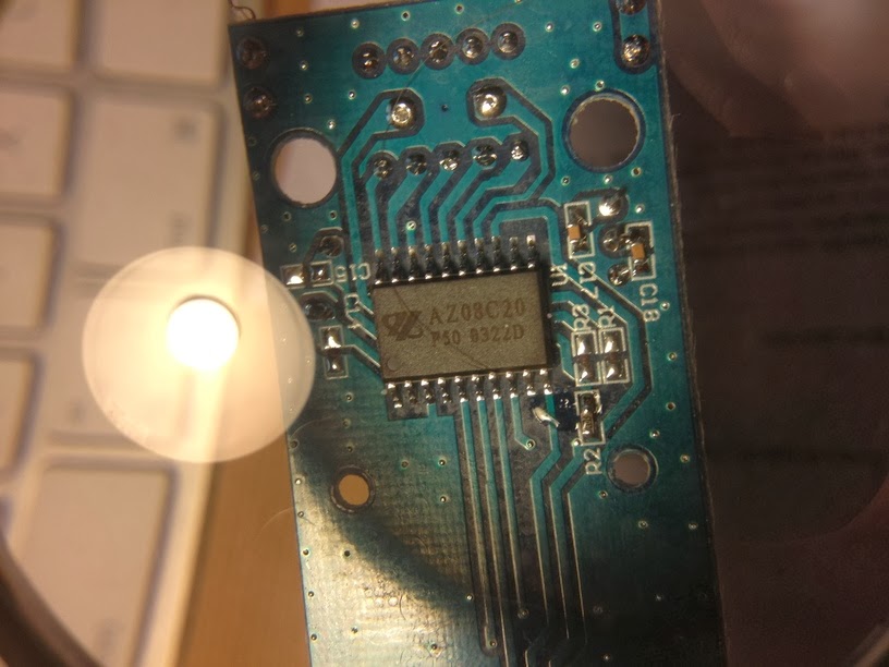
The remote control's IC:
AZ08C20 P50 0322D

Visualizing the signal

For this, I designed a GNURadio flowgraph. The source block provides the data from the SDR. Use either a UHD source for USRP devices from Ettus Research or else a OsmoSDR source for USB DVB-T dongles, BladeRF or HackRF. The data provided by the source is a stream of complex I/Q values, represented by pairs of 32bit floats. If you're not familiar with I/Q data, here are two excellent write-ups to learn about this data format and why it's used for SDRs. After reading this, you'll understand how the Complex to Mag^2 block is used to convert the complex I/Q samples into a real, scalar magnitude sample. The Threshold block is used to distinguish between HIGH and LOW states of the signal. Both real and discrete signals are input to the Scope Sink for the visusalization. The Wav File Sink is used to create a .wav file which can then be analyzed using common audio processing software such as Audacity.
GNURadio flowgraph used to visualize the signal

In the scope visusalization, we can see that the amplitude of the carrier frequency is modulated to form pulses of varying widths. This modulation scheme is called (binary) amplitude shift keying (ASK) or also sometimes On-Off-Keying (OOK). The encoding is a discretization of pulse width modulation (PWM), where pulses of different widths represent different information symbols. I determined the duration of the short (unit) pulse to be 533µs by measuring the number of samples across its width. The long pulse is twice as long: 2*533µs = 1.066ms. The blank between each pulse is of same duration as the unit. Effectively, each pulse starts after a period of 3*533µs = 1.6ms. Messages are continually sent in bursts of 25 pulse periods with a pause of 3.2ms inbetween, for a total of 128ms per message.

Replaying the signal (security implications)

Having recorded the signal as .wav file or as raw data, the flowgraph can be reversed to replay the messages. Choose the Wav File Source and connect it to your SDR sink (either UHD Sink or OsmoSDR Sink). This already suffices to trigger the switch. This indicates that there is no security whatsoever to protect the connectors from receiving messages not originating from the remote control. Also note that the number of possible different addresses (given by the combination of dip switch positions) is very low, 2^5 = 32, hence an attacker can very rapidly guess it by running through all possibilities.

Reverse-engineering

Assigning a short pulse to 0 and a long pulse to 1, I wrote down the different code patterns while pressing each button and systematically changing the dip switch positions. I could not identify every bit's meaning in these patterns, but I retrieved enough information to synthesize message which would actually trigger the switch. Here are some examples having all dip switches for the system code on HIGH:

                         DIPSW ????? ?????? B ?? EDCBA  ?
A         OFF            11111 00011 100101 0 00 00001 0
B         ON             11111 00011 100111 1 00 00010 0
B         OFF            11111 00011 101000 0 00 00010 0
C         ON             11111 00011 101001 1 00 00100 0
C         OFF            11111 00011 101010 0 00 00100 0
D         ON             11111 00011 101100 1 00 01000 0
D         OFF            11111 00011 101100 0 00 01000 0
Master    ON             11111 00011 101101 1 00 00000 0
Master    OFF            11111 00011 101110 0 00 00000 0


So obviously, the dip switches are reflected by the 5 first bits in the message. The 17th bit always correlates with the on (1) and off (0) button. Finally, bits 20-24 reflect the unit code. Concerning the remaining bits, I suspect bits 11-16 to be a counter and the rest to be padding.

Synthesizing the signal

After gathering all this information about the signal and the encoding, I decided to write a small GNURadio application with python to replicate the remote control in software by emitting the signal from the SDR. You can access the code here on github. The basic idea behind the modulator is to process the incoming stream of bits and converting them into I/Q samples. In order to describe the pulse train, I defined a intermediate 2-bit mapping according to following diagram, which will help you understand the code:
Intermediate 2-bit encoding of the pulse-widths

Using this mapping, a logical 0 is encoded with 01, a logical 1 is encoded with 10 and the pause between each burst is encoded with 00. Note that code 11 is never used. The GUI is designed to resemble the remote control's interface:
Application replicating
the remote control. Uses the
GNURadio framework

 That's it, I hope you enjoyed reading this. If you did, don't miss the flattr button ;-)

Sunday, October 27, 2013

Fun with Arduino

My team practices Scrum, an agile software development methodology. One of its commandments is the daily stand-up meeting: everyday, we meet to exchange our status. We take turns and everyone reports about his current activity. According to Scrum, the meeting shouldn't last more than 10-15 minutes. As the team has grown, sticking to this timebox got difficult. We started timing the turns, to help (or rather force) people to be more concise. First, we used a timer app on a smartphone, and noticed positive results. So we thought we needed a better timer, something similar to a chess clock.

A while ago I attended an Arduino class from FabLab Zurich. The class included an Arduino starter pack with some fun modules from AdaFruit like this 8x8 bicolor LED square pixel matrix, a buzzer and some push buttons. I thought I could use them to build our new timer. Sounded like fun at first, then I found out it really is :)

I first followed this video tutorial to build a custom shield, since I didn't want to solder the parts directly to the Arduino board. Before laying out the components, I tested the circuit on a breadboard:


I then proceeded to solder the parts on the shield; it was a good exercise since I'm not very skilled:


Here's the side view, where you can see the offset of the digital pins header, a design flaw of the Arduino UNO mentioned in the video tutorial or in this forum:


Finally, the front view where you can see the LED matrix, two push buttons and the buzzer:


The software for the countdown timer is hosted on github. It works like this: each participant has 64 seconds for his turn. Each second, a pixel lights up. At 2 thirds of the time, the pixels turn yellow. The last 8 pixels, the LEDs are red, indicating that you should conclude. The way the pixels light up is random for each turn. At the moment, there are 3 variants:
  • a simple row traverser
  • a random pixel filler
  • a spiral
I will try to extend the visualizations some more in the future. And I also hope for some contribution by my team mates :)

Tuesday, July 23, 2013

Perl TCP Listener

As a note to self, comes in handy whenever you're missing netcat:
#!/usr/bin/perl -w
use IO::Socket; 
use Net::hostent;              
$PORT = 6379;

$server = IO::Socket::INET->new( Proto     => 'tcp',
                                 LocalPort => $PORT,
                                 Listen    => 5,
                                 Reuse     => 1) or die "can't setup server" unless $server;

print "SERVER Waiting for client connection on port $PORT\n";

 while ($client = $server->accept()) {
  $client->autoflush(1);
  while ( <$client> ) {
    if (/quit|exit/i) { exit; }                           
    else { print $_;}
  }
  close $client; 
}

Tuesday, May 14, 2013

UPnP P0wnage

I've been enjoying some really good podcasts lately, in particular Security Now!. I was listening to episode 389 this morning about UPnP when I realized that I neither understood the technology, nor did I know if my home router provided this feature, if it was enabled and as such if it was prone to attacks discussed in the episode.

UPnP is a convenience service used to query and control network devices in a LAN without a hassle... meaning without proper authentication and access control. Which is perfectly fine in the context of your home LAN under the assumption that access will be granted only to trusted clients. The problem is: a lot of routers fail at blocking the UPnP port (UDP 1900) on the public WAN interface, making your router accessible to the entire internet. And then, most router products employ outdated, vulnerable UPnP frameworks for which a lot of exploits are publicly available. So think about the consequences: your router is your gateway to the internet, it handles all traffic to and from your laptops, tablets and iphones, and it is probably always on... it's the perfect jumpstation for man-in-the-middle attacks.

There are several online tools to check whether your router has UPnP enabled and if it is vulnerable to corresponding attacks, e.g. here or here. If you prefer testing it yourself, get a recent version of nmap, and type this into your console:
$ sudo nmap -Pn --script upnp-info.nse -p 1900 -sU 10.0.0.1

Starting Nmap 6.25 ( http://nmap.org ) at 2013-05-14 00:22 CEST
Nmap scan report for 10.0.0.1
Host is up (0.0010s latency).
PORT     STATE SERVICE
1900/udp open  upnp
| upnp-info: 
| 10.0.0.1
|     Server: Linux/2.6.12, UPnP/1.0, NETGEAR-UPNP/1.0
|     Location: http://10.0.0.1:5000/Public_UPNP_gatedesc.xml
|       Webserver: Linux/2.6.12 UPnP/1.0 NETGEAR-UPNP/1.0
|       Name: WGR614v9
|       Manufacturer: NETGEAR, Inc.
|       Model Descr: Wireless-G Router
|       Model Name: WGR614v9
|       Model Version: WGR614v9
|       Name: WAN Device
|       Manufacturer: NETGEAR, Inc.
|       Model Descr: Wireless-G Router
|       Model Name: WGR614v9
|       Model Version: WGR614v9
|       Name: WAN Connection Device
|       Manufacturer: NETGEAR, Inc.
|       Model Descr: Wireless-G Router
|       Model Name: WGR614v9
|_      Model Version: WGR614v9
MAC Address: C0:3F:0E:2D:12:F8 (Netgear)

The response to the discovery packet sent by nmap already contains various informations about the device, notably the webservice endpoint to which clients can address their UPnP calls (this is the actual vulnerable service). Also very interesting, the string "UPnP" occurs in the webserver banner. This makes it very easy to search for potential targets using a metadata search engine.

The best countermeasures for this insecurity is to keep your router firmware up to date and disable the UPnP feature. Better do it soon :-)

Saturday, January 5, 2013

The Warwalking Experiment


A couple of years ago I got curious about Wardriving but I never took time to go around sniffing for wireless networks on my own. Today I finally prepared setup which I used for a little walk in my neighborhood. This is what I packed in my backpack:

In order to use the scanner with the MacBook in the backpack, I used a little utility called InsomniaX which disables sleep mode when the lid is closed.

KisMAC is an application similar to Kismet that allows sniffing wireless networks in passive mode. Using the position data from the GPS receiver, it locates the detected access points and draws them on a map. It also creates a nice listing of network characteristics, such as the type of encryption and the currently connected clients. Here's a little summary of the data I sniffed today:

  • On a walking distance of approx 1 Kilometer, a total of 251 wireless access points were detected.
  • 11 access points use no encryption at all, meaning: free internet for everyone! Even if this sounds great, it's very insecure because anybody can intercept your network traffic and abuse your uplink, for which you are liable.
  • 15 access points are configured to use WEP encryption, which nowadays is equivalent to no encryption. WEP is vulnerable to several attacks, using the right tools it is possible to recover a WEP key within minutes.
  • 47 access points broadcast a network id (SSID) which leaks data about its owner. For example several access points were named after a local business or they contained the street address or simply just "John Doe's Network", which is a potential privacy issue makes social engineering really easy.
  • 43 access points use a brand name as SSID, e.g. "NETGEAR", "ZyXEL" or "DLink" which often is the default factory setting. This makes WPA attacks easier since the SSID is a component of the encryption key. Precomputed lookup tables for popular SSIDs can be used to speed up the process of cracking the pre-shared key.
  • The list of connected clients is also quite interesting. It is possible to derive the device vendor from the MAC addresses. It's no surprise that a great number of devices are manufactured by "Apple, Inc" since iOS-Devices are very popular in Switzerland. But there are also other devices such as Game Consoles ("Nintendo Co., Ltd.") and Wi-Fi Radios ("Slim Devices, Inc." which produce Logitech's Squeezebox).

All in all, this was quite instructive, and it makes me realize how many things you can do wrong when configuring an access point. Maybe the manufacturers should include a little booklet with best practices for securing wireless networks?

Tuesday, October 2, 2012

Seven Languages in Seven Weeks - Scala Day 2 Self Study

Hey there! I'm currently reading Seven Languages in Seven Weeks by Bruce A. Tate. As the title implies, this book explores seven different programming languages. Each chapter ends with a self study section. Here are the exercises of day 2 with the Scala programming language:

Use foldLeft to compute the total size of a list of strings:
Here are two variants, the first calls the foldLeft method (note the multiple parameter list, this is used for currying, i.e. partial function application) while the second is using the /: infix operator, which is in fact an overload of foldLeft:
  val list = List("foo", "bar", "hello", "world")
  list.foldLeft(0)((len, elem) => elem.size + len)//> res0: Int = 16
  (0 /: list) {(len, elem) => elem.size + len}    //> res1: Int = 16

Write a Censor trait with a method that will replace the curse words Shoot and Darn with Pucky and Beans alternatives. Use a map to store the curse words and their alternatives. Then, load the curse words and alternatives from a file:
The trait expects the curse words dictionary in the file words.txt:
Shoot:Pucky
Darn:Beans
The words are loaded line by line, each line is splitted at the : character and the values are stored in the substitions map. The replace method takes a text as input parameter, converts it as a list of words and applies the substitutions by looking up the map.
  trait Censor {
   val substitutions = new HashMap[String, String]
   
   Source.fromFile("/words.txt", "US-ASCII").getLines.foreach { line =>
    val elem = line.split(":", 2)
    substitutions += (elem(0) -> elem(1))
   }
   
   def replace(text: String): String = {
    text.split("\\s").map({word =>
     substitutions.getOrElse(word, word)
    }).reduceLeft((concat, word) => concat + " " + word)
   }
  }
Here's a simple example showing how the trait works:
  val censor = new Censor {}
  censor.replace("hello Darn world") //> res2: String = hello Beans world
Stay tuned, I'll soon be posting the 3rd study section about Scala.

Wednesday, September 26, 2012

vortex7

About a year ago I stumbled upon the Over The Wire hacker challenges and started solving the first set of levels (called vortex). Since then, I have been publishing my solutions in my blog. Here is vortex level 7:

The code

int main(int argc, char **argv)
{
        char buf[58];
        u_int32_t hi;
        if((hi = crc32(0, argv[1], strlen(argv[1]))) == 0xe1ca95ee) {
                strcpy(buf, argv[1]);
        } else {
                printf("0x%08x\n", hi);
        }
}

The vulnerability exposed in this code is a basic buffer overflow with two subtleties:

  1. The CRC of the buffer must equate to a given value (0xe1ca95ee)
  2. The buffer is rather small (58 bytes)

Manipulating the checksum

The cyclic redundancy check (CRC) computes a check value (or checksum), which is used to detect accidental changes in data, e.g. when transmitting over unreliable communication channels. With this error detecting code, the slightest change (i.e. bit-flip) in the input data results in a very different output pattern. As opposed to cryptographic hash functions like SHA1 or MD5, preimage resistance is not a property of CRC, it is not designed to withstand preimage attacks: given a checksum C, it is not hard to find an input m such that CRC(m) = C. As such, one shouldn't rely on it for integrity checks over insecure channels since it is very easy to manipulate it as is shown in the solution.

To solve this level, I chose to apply the CRC-reversing algorithm described in Reversing CRC – Theory and Practice, which by the way also contains a very nice introduction to CRC. The method consists in appending a 32-bit pattern to the buffer in order to adjust the CRC-remainder to the desired checksum. The same principle is proposed in the suggested lecture, CRC and how to Reverse it. But as opposed to the first approach which uses the inverse of the divisor polynomial, the bit pattern is derived using a system of equations.

Overflowing the buffer

This level contains a classic vulnerability which can easily be exploited to execute arbitrary code: a buffer overflow. The use of the strcpy standard library function to copy a buffer of data to another completely disregards the destination's capacity. If the source buffer is larger than the destination, all bytes will be copied, even though the destination's bound has been exceeded, and in doing so, subsequent structures in memory will be destroyed.

Intercepting the instruction pointer

Depending where the destination buffer is located in the process memory, it may be possible for an attacker to take influence on the program execution flow. In this case, the destination buffer is on the stack. By overflowing the buffer, copying bytes past its bound, the stored eip value will be overwritten. This is a pointer to the next instruction to return to after leaving the current stack frame, i.e. when returning from the current function call. With a meaningful value, it is possible to redirect the execution of the program to any executable location in memory.

Creating a shellcode

The payload we want to execute consists in a small fragment of x86 machine instructions, which perform 2-3 syscalls that allow us to run a shell:

  • geteuid()/setreuid() are used to set the effective user-id. The exploited binary runs with the suid-bit, which means the process is executed in the name of the file owner (the user that has read-privileges for the next level's password file).
  • execve() is called to run /bin/bash.

The original x86/asm code can be found here. Check out the Makefile to see how it is compiled and the raw instruction data is extracted. It is then necessary to encode the data to avoid specific patterns such as \0 bytes. I used metasploit's msfencode tool for this.

Executing arbitrary code

Since the buffer is rather small (58 bytes), it is difficult to dissimulate the malicious payload. An alternative way to include arbitrary data into the process memory is to define an evironment variable containing the data. It will be accessible from the beginning of the stack. The buffer must then overflow the saved eip value to point at the corresponding region in memory. Unfortunately, this address cannot be precisely deduced. Therefore, a common strategy consists in prepending a large number of nop instructions before the shellcode. This extends the landing platform of the target address thus increasing the probability of hitting the shellcode.

The exploit

The finalized exploit is available here. It is a C wrapper which prepares a shellcode and the buffer contents and calls the binary to exploit. I employed following methods from SAR-PR-2006-05 to implement the table driven CRC32 algorithm:

  • make_crc_table()
  • crc32_tabledriven()
  • fix_crc_end()

Since at first the resulting checksum values did not match the ones generated by vortex7 I additionally extracted the CRC32 table from the binary and stored them in crc_table_static. I realized that the vortex7 implementation actually uses 0x00000000 instead of 0xFFFFFFFF for INITXOR and FINALXOR.

The fix_crc_end() function adjusts the buffer such that its checksum eventually results in the desired value 0xe1ca95ee.

make_buffer() creates the data used to overflow the buffer. It contains a repetitive sequence of the target address. It allows to shift the sequence bytewise in order to adjust its alignment. make_payload() generates the buffer which contains the nop sled and the shellcode.

Finally, the wrapper executes vortex7, passing the address buffer as a command line argument and the payload in the environment variables.

The program expects two arguments:

  1. An offset for the target address, relative to the environment pointer taken from the current process (the wrapper).
  2. An alignment index (0-4) used to align the target address in the buffer.

Following arguments worked for me:

$ ./v7_wrapper 0 2
Using address: 0xFFFFD91F
$ whoami
vortex8

The password for the next level is then retrieved from the password file for the next level:

$ cat /etc/vortex_pass/vortex8 
X70A_gcgl

That's it! If you want to learn more about buffer overflows, I suggest you read Smashing the Stack for Fun and Profit by aleph1, originally posted in Phrack Magazine. Also have a look at my blog where I regularily publish vortex level solutions: blog.ant0i.net