Thursday, January 23, 2020

Analysis of a Fake Threema App

A couple of days ago there were reports of an app on the Google Playstore, which seemed to impersonate the Threema messenger app. Threema is a Swiss secure messaging service that uses end-to-end encryption to provide privacy to their users.


In the past, several fake apps were already observed targeting Swiss brands, like e.g. Bluewin. In that case, the app's purpose was to steal user credentials (login/password) from users that inadvertently downloaded it from the wrong developer. A more detailed description on the modus operandi can be found in a blog post by SWITCH-CERT.


Unfortunately, I failed to take a screenshot of the app while it was still available on the Playstore and before it was taken down by Google. But I remember that the counter had already reached 100+ downloads. Currently the app can still be downloaded from alternative sites like e.g. apkpure.com, which mirror all available apps from the Google Playstore. Each app in the Google Playstore is identified by a string in the form of a reverse domain name, in this case: com.wa.threema.


From the app description, we can see that the app was first published on January 9th 2020, meaning the app was available for more than ten days before it was reported to the Google abuse team and eventually removed.


So I went ahead and downloaded the APK file for analysis. First, I launched the emulator provided with the Android Studio development environment, dragged the APK into the virtual device and launched it. Meanwhile, I also started Burp Suite and changed the proxy settings of the emulator in order to intercept the network traffic. Unfortunately, this didn't work as expected because most network communication was destined to Google domains, which are protected by certificate pinning in the app. Therefore, I didn't follow up on the dynamic analysis, although it did allow me to take a couple of screenshots and to better understand the application logic:


I then used the JADX decompiler to open the APK file and recover its source code and other resources. First step is to analyse the AndroidManifest.xml, which contains a listing of relevant activities, especially the one that's called after the app startup: ar.codeslu.plax.MainActivity.


Looking at the code, we can see that the app makes use of Google's Firebase services, especially its noSQL database component, and we can already see what kind of entities are persisted on the backend: Global.USERS, Global.CHATS, Global.GROUPS and Global.CALLS. Also, an encryption object is created, it is initialized with Global.keyE and Global.salt, which are actually hardcoded values found in the ar.codeslu.plax.global.Global class (funny but irrelevant for the rest of the analysis):


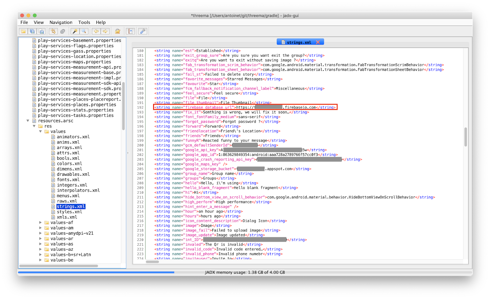
A glimpse at the string resources gives us information about the URLs used to connect to the Firebase database backend:


Thanks to Elliot Alderson's blog post on hacking the Donald Daters App, I learned how to access the insecure Firebase backend associated to the app, which of course contained all user, chat, group and call records, as defined in the MainActivity class. At the time of writing, the database contained 286 registered users, 15 chats and 8 calls.


Looking at the code, we can see that the app actually implements all functionality of a working messaging service, including audio and video calls. That's quite a lot of effort, assuming the app's intention is only phishing. Indeed, my assumption was that the app was attacking Threema's registration process, but I couldn't find evidence to back this claim. So what is this app intended for?

Based on the package name ar.codeslu.plax I figured that a similar app was being sold on a marketplace. And by that I mean you can actually buy the source code of the app for as less as 35 USD and customize it to offer your own chatting app on the Google Playstore:


It occurs you can even find free downloads of the code by googling somewhat:


There's also a more expensive license, that allows the buyer to charge its users and I assume that's the actual business model of the fake app:


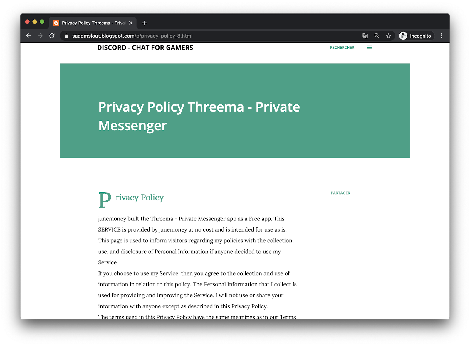
By looking for other apps by the same developer (junemoney, saadmslout@gmail.com) we see almost a dozen other chatting apps that have all been released approx. the same time and that also impersonate other popular messaging services like Discord, TextNow or Zalo, for which he has even written a corresponding privacy policy (I guess that's mandatory if you want to publish apps on the Playstore).


So in conclusion, from my point of view, the fake app's intention is not to steal user credentials, rather trick people into downloading the wrong app and have them pay subscriptions for usage of the app. (Other ideas? leave me a comment)

Anyhow, such apps often slip through Google Playstore's "quality assurance" during publication and are then made available to everyone for download :-/ But since such apps clearly violate Google's Developer Policies, anyone can report them as being abusive. Either because they are malicious, as in the case of the phishing app, or either because they infringe the intellectual property rights of others. In which case being logged into your Google account, you can go to the app's Playstore page, scroll down and report the app based on one of the two described violations.


Indicators of Compromise:
Filename: Threema Private Messenger_v1.4.2_apkpure.com.apk
SHA-256: a5422bc7f09c22a877f580119027ed83c6ba7ac12ae6647808b2ffddfcab7124

Wednesday, September 21, 2016

36 15 Framboise


As a boy while visiting family in France, one of the things I was very excited about was the Minitel that everybody had at home. It was a very popular videotex network in the 80s and 90s providing a multitude of services unbelievably similar to today's online experience. This compilation of ads and news reports give a good feel of what the Minitel had to offer. Today, it is often considered as a precursor of the world wide web.

So, to satisfy my nostalgic feelings, I bought a Minitel on Ebay. Although the service was retired in 2012, there are still plenty of devices on sale with prices ranging from 20€ for the most common models (e.g. Minitel 1B TELIC) to several hundreds € for the earlier/rarer models. The device suffered some cracks in the shell from shipping, but fortunately it still works!

Although the service is discontinued, and even if not living in France, a Minitel can still be operated in useful ways. The Minitel is a so-called dumb-terminal. It is used to access services running on distant systems which are accessed via the telephone network. So the Minitel has an integrated modem. But it can also interface with local devices, via a serial port available on the back. There are plenty of blog posts explaining how to do this, just google for "minitel linux terminal". Since I'm also fond of Raspberry Pi, this is the mandatory I-hooked-a-Minitel-to-my-Raspberry-Pi blog post!


I won't delve into too many technical details about the serial port adaptation, since there are enough resources about it online, but let me just describe the challenges I faced. First of all, the Minitel expects a male 5 pin DIN connector, not the usual DE-9 to interface with the serial port. They call it "Prise Péri-Informatique". I used a conventional MIDI patch cable, cut it in half and resoldered the pins to match the Minitel TX and RX leads.


Also, since I didn't want to get my hands too dirty - although I should practice some more soldering - I used the bi-directional level converter from sparkfun to adapt the 3.3V TTL signal level from the Raspberry Pi to the 5-15V levels of the Minitel (and vice-versa). There are many blog posts explaining how to implement this using a simple circuit with a couple of resistors and transistors.


I took some time to analyze the signal with an oscilloscope and interpret the serial protocol. When no characters are transmitted, the idle level is high. The asynchronous transmission starts with the start bit (low), continues with the 7 bit ASCII character value (most significant bit first), an even parity bit and finally ends with a stop bit (high). From the measurement we can see that a symbol is transmitted in 208 microseconds. This value inverted corresponds to the baud rate of 4800 bps. In this case, the transmitted character was a lowercase 'e' (0b01100101 or 0x65).


Finally, the last challenge I encountered was the fact that Raspbian, the standard debian-based Linux distro for Raspberry Pi switched to systemd. Most blog posts still refer to /etc/inittab to install the serial getty. Under systemd, it's a bit tricky. Here's my configuration under /etc/systemd/system/serial-getty@ttyAMA0.service:

# This file is part of systemd.
#
# systemd is free software; you can redistribute it and/or modify it
# under the terms of the GNU Lesser General Public License as published by
# the Free Software Foundation; either version 2.1 of the License, or
# (at your option) any later version.

[Unit]
Description=Serial Getty on %I
Documentation=man:agetty(8) man:systemd-getty-generator(8)
Documentation=http://0pointer.de/blog/projects/serial-console.html
BindsTo=dev-%i.device
After=dev-%i.device systemd-user-sessions.service plymouth-quit-wait.service
After=rc-local.service

# If additional gettys are spawned during boot then we should make
# sure that this is synchronized before getty.target, even though
# getty.target didn't actually pull it in.
Before=getty.target
IgnoreOnIsolate=yes

[Service]
ExecStart=-/sbin/agetty -c ttyAMA0 4800 m1b-x80
Type=idle
Restart=always
UtmpIdentifier=%I
TTYPath=/dev/%I
TTYReset=yes
TTYVHangup=yes
KillMode=process
IgnoreSIGPIPE=no
SendSIGHUP=yes

[Install]
WantedBy=getty.target


I also used the Minitel 1B terminfo file of Alexandre Montaron and installed it as follows:

$ tic mntl.ti -dir /etc/terminfo


Here a screenshot of the working system with the output of the top command:


10 years ago, I got a hand on the "Spécification Techniques d'Utilisation du Minitel 1B" (STUM), a 200 page specification of the Minitel and it's building components (modem, keyboard, screen, serial port) as well as the different modes of operation ("Standard Télétel" or "Standard Téléinformatique ASCII"). It has shown very helpful to understand the inner workings of the device.


Finally, here are some links you might want to check out if you want to find out more about Minitel:

Thursday, June 5, 2014

How to Prevent your ISP from Controlling your SOHO Router (TR-069)

I freaked out a bit a lot when learning about TR-069 from Shahar Tal's great talk at this year's area41 security conference. Basically, if your router features this interface, your ISP can do all sorts of things like read and alter the configuration but also upgrade the firmware without your knowing.
Being a Swisscom client, I use a Centro Piccolo aka Motorola Netopia 7640 VDSL Modem. I knew that there had to be some kind of remote management, e.g. since resetting the router password is done via the the Swisscom customer website instead of directly on the router's administration interface. Then, there is no obvious configuration option refering to TR-069 nor CWMP in the admin interface. But: you can access extended settings by telneting the router. Here's the menu options you have to select to disable CWMP:

$ telnet 192.168.1.1
Trying 192.168.1.1...
Connected to dsldevice.home.
Escape character is '^]'.

login: admin
Password: **********

Terminal shell v1.0
Copyright (C) 2011 Motorola, Inc.  All rights reserved.
Motorola Netopia Model 7640-47 Annex A VDSL2 IAD
Running Netopia SOC OS version 9.0.10 (build h2d8)
ADSL/VDSL capable
(admin completed login: Admin account with read/write access.)

Centro_piccolo> configure

Config Mode v1.3
Centro_piccolo (top)>> management cwmp
Centro_piccolo (management cwmp)>> view
    cwmp
      enable on
      acs-url "https://rms.bluewin.ch:8443/cwmpWeb/CPEMgt"
      acs-username "********************************"
      acs-password "********************************"
Centro_piccolo (management cwmp)>> enable
Centro_piccolo (management cwmp enable)>> set
      enable (on) [ off | on ]: off

Here you can also see the URL of the ACS (the ISP's configuration server). Save before quitting, you should be then safe from any snooping from your ISP. Oh, and while you're at it, try the undocumented magic command in the telnet prompt ;-)

Saturday, February 1, 2014

Experimenting with Software Defined Radio

In this blog post, I will describe my first project experimenting with a software defined radio (SDR). For those of you new to this technology, think of it as an RF frontend to your computer, which performs most signal processing from digitized radio waves in software. Hence, virtually any radio communication system can be implemented given capable software. There is already a plethora of projects for a variety of RF applications related to industry or consumer standards. The CGRAN maintains a list of projects, have a look at it to get an idea of what's all possible.

The test hardware

So, to become acquainted with the SDR, I chose to analyze this simple RF controlled power switch system I found at my local supermarket. The package contains three radio controlled connectors with a pass through socket for the electrical appliance. The remote control individually switches the connectors on and off by pressing on the corresponding buttons. When switching a controller on and off, the clicking sound of a relay is clearly audible.
Power Switch System 1204380 3M from Steffen AG

Anatomy of the controller

The remote and the connectors are both configured via dip switches inside the enclosure. The address scheme comprises a 5 bit system code (positions 1 to 5 in the pictures below), commonly used by all devices. Also, a unit code (positions A-E) is assigned to each of the connectors to individually address them. Interestingly enough, position E is not provided on the remote, instead, there is a master on/off switch that addresses all units at once.
Dip switches for the selection of the system code (common to all devices)
and the unit code (individual to each connector)
On the back of the remote control, the model number and most interestingly, the operating frequency 433.92MHz are engraved on the enclosure. Within the enclosure, a PCB with a single IC labeled AZ08C20, P50 0322D. Unfortunately, I couldn't find any specification for this chip that would ease the task of analyzing the control signal. There are specifications publicly available for similar ICs that helped me grasp the encoding principle: for example Princeton Technologies PT2262 and PT2272, and Holtek HT12A and HT12E.
 
The remote control's IC:
AZ08C20 P50 0322D

Visualizing the signal

For this, I designed a GNURadio flowgraph. The source block provides the data from the SDR. Use either a UHD source for USRP devices from Ettus Research or else a OsmoSDR source for USB DVB-T dongles, BladeRF or HackRF. The data provided by the source is a stream of complex I/Q values, represented by pairs of 32bit floats. If you're not familiar with I/Q data, here are two excellent write-ups to learn about this data format and why it's used for SDRs. After reading this, you'll understand how the Complex to Mag^2 block is used to convert the complex I/Q samples into a real, scalar magnitude sample. The Threshold block is used to distinguish between HIGH and LOW states of the signal. Both real and discrete signals are input to the Scope Sink for the visusalization. The Wav File Sink is used to create a .wav file which can then be analyzed using common audio processing software such as Audacity.
GNURadio flowgraph used to visualize the signal

In the scope visusalization, we can see that the amplitude of the carrier frequency is modulated to form pulses of varying widths. This modulation scheme is called (binary) amplitude shift keying (ASK) or also sometimes On-Off-Keying (OOK). The encoding is a discretization of pulse width modulation (PWM), where pulses of different widths represent different information symbols. I determined the duration of the short (unit) pulse to be 533µs by measuring the number of samples across its width. The long pulse is twice as long: 2*533µs = 1.066ms. The blank between each pulse is of same duration as the unit. Effectively, each pulse starts after a period of 3*533µs = 1.6ms. Messages are continually sent in bursts of 25 pulse periods with a pause of 3.2ms inbetween, for a total of 128ms per message.

Replaying the signal (security implications)

Having recorded the signal as .wav file or as raw data, the flowgraph can be reversed to replay the messages. Choose the Wav File Source and connect it to your SDR sink (either UHD Sink or OsmoSDR Sink). This already suffices to trigger the switch. This indicates that there is no security whatsoever to protect the connectors from receiving messages not originating from the remote control. Also note that the number of possible different addresses (given by the combination of dip switch positions) is very low, 2^5 = 32, hence an attacker can very rapidly guess it by running through all possibilities.

Reverse-engineering

Assigning a short pulse to 0 and a long pulse to 1, I wrote down the different code patterns while pressing each button and systematically changing the dip switch positions. I could not identify every bit's meaning in these patterns, but I retrieved enough information to synthesize message which would actually trigger the switch. Here are some examples having all dip switches for the system code on HIGH:

                         DIPSW ????? ?????? B ?? EDCBA  ?
A         OFF            11111 00011 100101 0 00 00001 0
B         ON             11111 00011 100111 1 00 00010 0
B         OFF            11111 00011 101000 0 00 00010 0
C         ON             11111 00011 101001 1 00 00100 0
C         OFF            11111 00011 101010 0 00 00100 0
D         ON             11111 00011 101100 1 00 01000 0
D         OFF            11111 00011 101100 0 00 01000 0
Master    ON             11111 00011 101101 1 00 00000 0
Master    OFF            11111 00011 101110 0 00 00000 0


So obviously, the dip switches are reflected by the 5 first bits in the message. The 17th bit always correlates with the on (1) and off (0) button. Finally, bits 20-24 reflect the unit code. Concerning the remaining bits, I suspect bits 11-16 to be a counter and the rest to be padding.

Synthesizing the signal

After gathering all this information about the signal and the encoding, I decided to write a small GNURadio application with python to replicate the remote control in software by emitting the signal from the SDR. You can access the code here on github. The basic idea behind the modulator is to process the incoming stream of bits and converting them into I/Q samples. In order to describe the pulse train, I defined a intermediate 2-bit mapping according to following diagram, which will help you understand the code:
Intermediate 2-bit encoding of the pulse-widths

Using this mapping, a logical 0 is encoded with 01, a logical 1 is encoded with 10 and the pause between each burst is encoded with 00. Note that code 11 is never used. The GUI is designed to resemble the remote control's interface:
Application replicating
the remote control. Uses the
GNURadio framework

 That's it, I hope you enjoyed reading this. If you did, don't miss the flattr button ;-)

Sunday, October 27, 2013

Fun with Arduino

My team practices Scrum, an agile software development methodology. One of its commandments is the daily stand-up meeting: everyday, we meet to exchange our status. We take turns and everyone reports about his current activity. According to Scrum, the meeting shouldn't last more than 10-15 minutes. As the team has grown, sticking to this timebox got difficult. We started timing the turns, to help (or rather force) people to be more concise. First, we used a timer app on a smartphone, and noticed positive results. So we thought we needed a better timer, something similar to a chess clock.

A while ago I attended an Arduino class from FabLab Zurich. The class included an Arduino starter pack with some fun modules from AdaFruit like this 8x8 bicolor LED square pixel matrix, a buzzer and some push buttons. I thought I could use them to build our new timer. Sounded like fun at first, then I found out it really is :)

I first followed this video tutorial to build a custom shield, since I didn't want to solder the parts directly to the Arduino board. Before laying out the components, I tested the circuit on a breadboard:


I then proceeded to solder the parts on the shield; it was a good exercise since I'm not very skilled:


Here's the side view, where you can see the offset of the digital pins header, a design flaw of the Arduino UNO mentioned in the video tutorial or in this forum:


Finally, the front view where you can see the LED matrix, two push buttons and the buzzer:


The software for the countdown timer is hosted on github. It works like this: each participant has 64 seconds for his turn. Each second, a pixel lights up. At 2 thirds of the time, the pixels turn yellow. The last 8 pixels, the LEDs are red, indicating that you should conclude. The way the pixels light up is random for each turn. At the moment, there are 3 variants:
  • a simple row traverser
  • a random pixel filler
  • a spiral
I will try to extend the visualizations some more in the future. And I also hope for some contribution by my team mates :)

Tuesday, July 23, 2013

Perl TCP Listener

As a note to self, comes in handy whenever you're missing netcat:
#!/usr/bin/perl -w
use IO::Socket; 
use Net::hostent;              
$PORT = 6379;

$server = IO::Socket::INET->new( Proto     => 'tcp',
                                 LocalPort => $PORT,
                                 Listen    => 5,
                                 Reuse     => 1) or die "can't setup server" unless $server;

print "SERVER Waiting for client connection on port $PORT\n";

 while ($client = $server->accept()) {
  $client->autoflush(1);
  while ( <$client> ) {
    if (/quit|exit/i) { exit; }                           
    else { print $_;}
  }
  close $client; 
}

Tuesday, May 14, 2013

UPnP P0wnage

I've been enjoying some really good podcasts lately, in particular Security Now!. I was listening to episode 389 this morning about UPnP when I realized that I neither understood the technology, nor did I know if my home router provided this feature, if it was enabled and as such if it was prone to attacks discussed in the episode.

UPnP is a convenience service used to query and control network devices in a LAN without a hassle... meaning without proper authentication and access control. Which is perfectly fine in the context of your home LAN under the assumption that access will be granted only to trusted clients. The problem is: a lot of routers fail at blocking the UPnP port (UDP 1900) on the public WAN interface, making your router accessible to the entire internet. And then, most router products employ outdated, vulnerable UPnP frameworks for which a lot of exploits are publicly available. So think about the consequences: your router is your gateway to the internet, it handles all traffic to and from your laptops, tablets and iphones, and it is probably always on... it's the perfect jumpstation for man-in-the-middle attacks.

There are several online tools to check whether your router has UPnP enabled and if it is vulnerable to corresponding attacks, e.g. here or here. If you prefer testing it yourself, get a recent version of nmap, and type this into your console:
$ sudo nmap -Pn --script upnp-info.nse -p 1900 -sU 10.0.0.1

Starting Nmap 6.25 ( http://nmap.org ) at 2013-05-14 00:22 CEST
Nmap scan report for 10.0.0.1
Host is up (0.0010s latency).
PORT     STATE SERVICE
1900/udp open  upnp
| upnp-info: 
| 10.0.0.1
|     Server: Linux/2.6.12, UPnP/1.0, NETGEAR-UPNP/1.0
|     Location: http://10.0.0.1:5000/Public_UPNP_gatedesc.xml
|       Webserver: Linux/2.6.12 UPnP/1.0 NETGEAR-UPNP/1.0
|       Name: WGR614v9
|       Manufacturer: NETGEAR, Inc.
|       Model Descr: Wireless-G Router
|       Model Name: WGR614v9
|       Model Version: WGR614v9
|       Name: WAN Device
|       Manufacturer: NETGEAR, Inc.
|       Model Descr: Wireless-G Router
|       Model Name: WGR614v9
|       Model Version: WGR614v9
|       Name: WAN Connection Device
|       Manufacturer: NETGEAR, Inc.
|       Model Descr: Wireless-G Router
|       Model Name: WGR614v9
|_      Model Version: WGR614v9
MAC Address: C0:3F:0E:2D:12:F8 (Netgear)

The response to the discovery packet sent by nmap already contains various informations about the device, notably the webservice endpoint to which clients can address their UPnP calls (this is the actual vulnerable service). Also very interesting, the string "UPnP" occurs in the webserver banner. This makes it very easy to search for potential targets using a metadata search engine.

The best countermeasures for this insecurity is to keep your router firmware up to date and disable the UPnP feature. Better do it soon :-)