
Showing posts with label python. Show all posts

Monday, January 27, 2025

2024 Swisscom security.txt Challenge Writeup

For the last couple of years, I've been planting a CTF-like challenge as an easter egg in Swisscom's security.txt file (RFC 9116). The current challenge is here: https://www.swisscom.ch/.well-known/security.txt. All challenges are also archived on Github: https://github.com/swisscom/securitytxt. I thought it was about time to provide the solutions to the past challenges. You can find the writeup for 2023 and 2022 in my last posts here and here. Now let's continue with year 2024. You were given the following string:

aHR0cHM6Ly9naXRodWIuY29tL3N3aXNzY29tL3NlY3VyaXR5d
Hh0L2Jsb2IvbWFzdGVyL2NoYWxsZW5nZXMvMjAyNC5nYg==
As in the 2022 challenge, experienced blue teamers will quickly recognize the Base64 encoding as well as guess it's a URL, judging from the prefix. The decoded value links to a file named 2024.gb on the Swisscom github repository. A quick identification using the linux file command tells us it's a Nintendo Game Boy ROM:

$ file 2024.gb
2024.gb: Game Boy ROM image: "DEBRUIJN" (Rev.01) [ROM ONLY], ROM: 256Kbit
There is a myriad of Game Boy emulators to run the ROM on, here are only a few suggestions:

  • Emulicious multi-system emulator written in Java for Windows, Linux, MacOS, which provides nice debugging capabilities
  • GameBoy Online emulator written in Javascript that you can run off your browser
  • MAME (Multi Arcade Machine Emulator), the mother of all emulators

Here are some screenshots of the results, running on the different emulators. The screen shows an electronic circuit composed of a PIN-pad, a 4-digit 7-segment display, some ICs labeled PBKDF2, ROM, AES and VRAM.

Using the Game Boy's D-pad, you can move a cursor over the digits of the PIN-pad. When pressing the A or B button, the digit under the cursor will be left-shifted on the 7-segment display. The START button changes the screen to something, which looks like static from an old TV set. Pressing START again will restore the initial screen. One can repeat the operation and notice, that the static pattern changes for every value in the 7-segment display. However, the pattern is not totally random, it seems to have a repeated cycle and you can almost discern letters in the middle, which reminds of the ECB pinguin.

Therefore, the solution of the challenge seems to be a 4-digit combination, which will unlock the second screen. Initial guesses like for example 1234, 1337, or 4711 all fail, so there must be more to it. There are two obvious strategies to solve this crackme:

  1. Reverse-engineering the ROM image, to analyse the encryption mechanism
  2. Or, due to the limited numbers of combinations, brute-force all 10'000 PINs

I will opt for the latter. To implement the brute-force strategy, we need a scriptable emulator, that allows for automation of the PIN-pad inputs, and validation of the resulting screen. After some online search, the choice quickly falls on PyBoy, a Game Boy emulator written in Python, which provides an application programming interface (API). PyBoy is a very interesting project that is also used to build AIs for speedrunning.

After getting familiar with the API by studying the provided examples and the documentation, we'll need to implement some basic blocks to interact with the game elements:

  • The function move_to(target_digit) is used to move the cursor from the current position to the specified target digit using the shortest path. Note that the * and # keys are not reachable, therefore, some care needs to be taken for key 0, either as source or destination, since it lies in-between.
  • We need to keep track of the 4-digits of the 7-segment display. The current value is stored in the shift_reg array and the shift(n) function is used to insert a new digit.
  • Timing is important when pressing buttons, as the triggered operations will require a different number of CPU cycles (called ticks in PyBoy). We need to identify the least number of ticks for each operation in order to optimize the individual PIN validation cycle. 

Using these primitives, we can now proceed with the actual brute force logic. The obvious approach is to iterate through the whole range of 4-digit PINs, starting from 0000, 0001, 0002, ..., until we finally reach 9999. This means that for every iteration, we feed 4 digits into the shift register, check the screen output, and repeat. However, there's a faster way. Remember the output of the file command? The ROM is titled DEBRUIJN, after the Dutch mathematician, famously known for the de Bruijn sequence:

A de Bruijn sequence is a cyclic sequence that contains every possible combination of a given set of symbols (like 0s and 1s) of a certain length exactly once. For example, for binary symbols and combinations of length 2, the sequence "0011" works because it includes all pairs—00, 01, 10, 11—without repetition. It's used in areas like computer science, data compression, and DNA sequencing because it efficiently encodes all possible combinations in the shortest way possible.

Other applications of de Bruijn in cyber security are for example: Depixelization, hacking garage doors, or finding the offset for overflow exploits. We will need the sequence of order 4 over the digits 0-9. I used the Python code from Wikipedia for this. This will reduce each iteration to feeding only 1 digit into the shift register before checking the screen output.

The last task remains: how can we actually identify the "right" screen output? In a straightforward approach, we could just simply take a screenshot of the result of every iteration, the filename being the current PIN. Visual review of the 10k screenshots as thumbnails will only take a couple of minutes. On the other hand, we can assume that the right screen will not be scrambled, meaning it has less entropy than all wrong screens. Hence, we only need to keep track of the screen with the least entropy, saving lots of inodes on the way.

You can find the Python code on my Github repo, it takes less than 2 mins to solve the challenge on a generic laptop.


The first 10 people who wrote a message to the e-mail address with the solution received some Swisscom swag as a reward. Note: the e-mail address was chosen as a reference to the 1999 hacker/cyberpunk movie The Matrix, following the nomenclature of the meeting rooms in the Swisscom Cyber Defence offices. Any other references are explicitly excluded.


Saturday, February 1, 2014

Experimenting with Software Defined Radio

In this blog post, I will describe my first project experimenting with a software defined radio (SDR). For those of you new to this technology, think of it as an RF frontend to your computer, which performs most signal processing from digitized radio waves in software. Hence, virtually any radio communication system can be implemented given capable software. There is already a plethora of projects for a variety of RF applications related to industry or consumer standards. The CGRAN maintains a list of projects, have a look at it to get an idea of what's all possible.

The test hardware

So, to become acquainted with the SDR, I chose to analyze this simple RF controlled power switch system I found at my local supermarket. The package contains three radio controlled connectors with a pass through socket for the electrical appliance. The remote control individually switches the connectors on and off by pressing on the corresponding buttons. When switching a controller on and off, the clicking sound of a relay is clearly audible.
Power Switch System 1204380 3M from Steffen AG

Anatomy of the controller

The remote and the connectors are both configured via dip switches inside the enclosure. The address scheme comprises a 5 bit system code (positions 1 to 5 in the pictures below), commonly used by all devices. Also, a unit code (positions A-E) is assigned to each of the connectors to individually address them. Interestingly enough, position E is not provided on the remote, instead, there is a master on/off switch that addresses all units at once.
Dip switches for the selection of the system code (common to all devices)
and the unit code (individual to each connector)
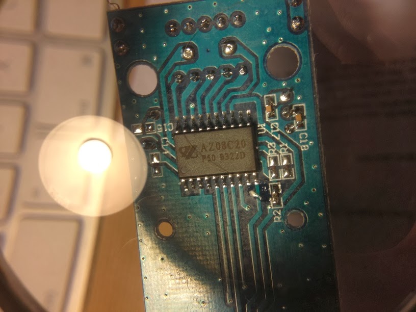
On the back of the remote control, the model number and most interestingly, the operating frequency 433.92MHz are engraved on the enclosure. Within the enclosure, a PCB with a single IC labeled AZ08C20, P50 0322D. Unfortunately, I couldn't find any specification for this chip that would ease the task of analyzing the control signal. There are specifications publicly available for similar ICs that helped me grasp the encoding principle: for example Princeton Technologies PT2262 and PT2272, and Holtek HT12A and HT12E.
 
The remote control's IC:
AZ08C20 P50 0322D

Visualizing the signal

For this, I designed a GNURadio flowgraph. The source block provides the data from the SDR. Use either a UHD source for USRP devices from Ettus Research or else a OsmoSDR source for USB DVB-T dongles, BladeRF or HackRF. The data provided by the source is a stream of complex I/Q values, represented by pairs of 32bit floats. If you're not familiar with I/Q data, here are two excellent write-ups to learn about this data format and why it's used for SDRs. After reading this, you'll understand how the Complex to Mag^2 block is used to convert the complex I/Q samples into a real, scalar magnitude sample. The Threshold block is used to distinguish between HIGH and LOW states of the signal. Both real and discrete signals are input to the Scope Sink for the visusalization. The Wav File Sink is used to create a .wav file which can then be analyzed using common audio processing software such as Audacity.
GNURadio flowgraph used to visualize the signal

In the scope visusalization, we can see that the amplitude of the carrier frequency is modulated to form pulses of varying widths. This modulation scheme is called (binary) amplitude shift keying (ASK) or also sometimes On-Off-Keying (OOK). The encoding is a discretization of pulse width modulation (PWM), where pulses of different widths represent different information symbols. I determined the duration of the short (unit) pulse to be 533µs by measuring the number of samples across its width. The long pulse is twice as long: 2*533µs = 1.066ms. The blank between each pulse is of same duration as the unit. Effectively, each pulse starts after a period of 3*533µs = 1.6ms. Messages are continually sent in bursts of 25 pulse periods with a pause of 3.2ms inbetween, for a total of 128ms per message.

Replaying the signal (security implications)

Having recorded the signal as .wav file or as raw data, the flowgraph can be reversed to replay the messages. Choose the Wav File Source and connect it to your SDR sink (either UHD Sink or OsmoSDR Sink). This already suffices to trigger the switch. This indicates that there is no security whatsoever to protect the connectors from receiving messages not originating from the remote control. Also note that the number of possible different addresses (given by the combination of dip switch positions) is very low, 2^5 = 32, hence an attacker can very rapidly guess it by running through all possibilities.

Reverse-engineering

Assigning a short pulse to 0 and a long pulse to 1, I wrote down the different code patterns while pressing each button and systematically changing the dip switch positions. I could not identify every bit's meaning in these patterns, but I retrieved enough information to synthesize message which would actually trigger the switch. Here are some examples having all dip switches for the system code on HIGH:

                         DIPSW ????? ?????? B ?? EDCBA  ?
A         OFF            11111 00011 100101 0 00 00001 0
B         ON             11111 00011 100111 1 00 00010 0
B         OFF            11111 00011 101000 0 00 00010 0
C         ON             11111 00011 101001 1 00 00100 0
C         OFF            11111 00011 101010 0 00 00100 0
D         ON             11111 00011 101100 1 00 01000 0
D         OFF            11111 00011 101100 0 00 01000 0
Master    ON             11111 00011 101101 1 00 00000 0
Master    OFF            11111 00011 101110 0 00 00000 0


So obviously, the dip switches are reflected by the 5 first bits in the message. The 17th bit always correlates with the on (1) and off (0) button. Finally, bits 20-24 reflect the unit code. Concerning the remaining bits, I suspect bits 11-16 to be a counter and the rest to be padding.

Synthesizing the signal

After gathering all this information about the signal and the encoding, I decided to write a small GNURadio application with python to replicate the remote control in software by emitting the signal from the SDR. You can access the code here on github. The basic idea behind the modulator is to process the incoming stream of bits and converting them into I/Q samples. In order to describe the pulse train, I defined a intermediate 2-bit mapping according to following diagram, which will help you understand the code:
Intermediate 2-bit encoding of the pulse-widths

Using this mapping, a logical 0 is encoded with 01, a logical 1 is encoded with 10 and the pause between each burst is encoded with 00. Note that code 11 is never used. The GUI is designed to resemble the remote control's interface:
Application replicating
the remote control. Uses the
GNURadio framework

 That's it, I hope you enjoyed reading this. If you did, don't miss the flattr button ;-)